Stereo Camera Calibration and Depth Estimation from Stereo Images
Well, when we capture photos in 2D, all the depth information is lost due to a process called Perspective projection. When an image is taken, it is converted from 3D to 2D, it is presented on a 2D plane where the distance of each point (or pixel) away from the camera lens is simply non-existent. This leads to loss of depth information. But this is precisely the information we need in order to perform 3D reconstruction with 2D images. The key to our solution lies in using a second camera to take a picture of the same object and compare each image to extract depth information.

Our eyes are similar to two cameras. Since they look at an image from different angles, they can compute the difference between the two point of view and establish a distance estimation. Using both eyes and staring at an object heads-on creates depth because our own vision appears to converge. It’s similar to a perspective photo where all parallel lines intersect at some far-off horizon point.
A stereo vision system has two cameras located at a known distance and take pictures of the scene at the same time. Using the geometry of the cameras, we can apply algorithms and create the geometry of the environment. In such systems, the location and optical parameters of each separate camera must be calibrated so that triangulation methods can be used to determine the correspondence between pixels in each image.
In practice, stereo vision is realized in four stages with the help of two cameras:
1. Distortion Correction — Removal of radial and tangential distortions of the lens on images to get an undistorted image.
2. Angles and distances adjustment between cameras in the rectification process. The result is line-aligned which means two images of a plane are coplanar and their lines are aligned in the same direction and have the same y-coordinate.
3. The point matching process — a search for correspondences between the points of the left and right cameras. It leads to a disparity map — where values correspond to differences in the x-coordinate of the image for the same point of the left and right cameras.
4. As a result, having a geometrical arrangement of cameras, we produce a disparity map triangulation. This is the stage of reprojection, which forms a depth map, that is, the desired 3D scene.
For the first two stages, one must first calculate the configuration parameters of a pair of cameras.
Camera Calibration
Camera calibration is the estimation of the parameters of a camera, parameters about the camera required to determine an accurate relationship between a 3D point in the real world and its corresponding 2D projection (pixel) in the image captured by that calibrated camera.
The major purpose of camera calibration is to remove the distortions in the image and thereby establish a relation between image pixels and real world dimensions. In order to remove the distortion we need to find the intrinsic parameters in the intrinsic matrix K and the distortion parameters.
Image Distortion
A distortion can be radial or tangential. Calibration helps to undistort an image.
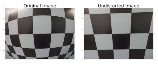
Radial distortion: Radial distortion occurs when the light rays bend more at the edges of the lens than the optical center of the lens. It essentially makes straight lines appear as slightly curved within an image.

x-distorted = x(1 + k1*r² + k2*r⁴ + k3*r⁶)
y-distorted = y(1 + k1*r² + k2*r⁴ + k3*r⁶)
x, y — undistorted pixels that are in image coordinate system.
k1, k2, k3 — radial distortion coefficients of the lens.
Tangential distortion: This form of distortion occurs when the lens of the camera being utilized is not perfectly aligned i.e. parallel with the image plane. This makes the image to be extended a little while longer or tilted, it makes the objects appear farther away or even closer than they actually are.

x-distorted = x + [2 * p1 * x * y + p2 * (r² + 2 * x²)]
y-distorted = y + [p1 * (r² + 2 *y²) + 2 * p2 * x * y]
x, y — undistorted pixels that are in image coordinate system.
p1, p2 — tangential distortion coefficients of the lens.
This distortion can be captured by five numbers called Distortion Coefficients, whose values reflect the amount of radial and tangential distortion in an image.

We need intrinsic and extrinsic parameters of camera to find distortion coefficient parameters (k1, k2, k3, p1, p2). The intrinsic parameters are camera-specific (same parameters for same camera) that are focal length (fx, fy) and optical centers (cx, cy).
Intrinsic parameters depend only on camera characteristics while extrinsic parameters depend on camera position.

The matrix containing this parameters is referred to as the camera matrix.
Mapping of 3D world coordinate to 2D Image coordinate
Calibration maps a 3D point (in the world) with [X, Y, Z] coordinates to a 2D Pixel with [X, Y] coordinates.
With calibrated camera, we can transformation world coordinates to pixel coordinates going through camera coordinates.

- Extrinsic calibration converts World Coordinates to Camera Coordinates. The extrinsic parameters are called R (rotation matrix) and T (translation matrix).
- Intrinsic calibration converts Camera Coordinates to Pixel Coordinates. It requires inner values for the camera such as focal length, optical center. The intrinsic parameter is a matrix we call K.
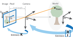
In the process of camera calibration, we have two formulas to get a point O from the world to the pixel space:
- World to Camera Conversion

The essential matrix is the part of the basic fundamental matrix that is only related to external parameters.
- Camera to Image Conversion

- World to Image Conversion

However the matrices doesn’t match. Due to this world matrix needs to be modified from [X Y Z] to [X Y Z 1]. This “1” is called a homogeneous coordinate.
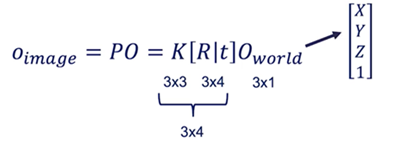
P = [R|T] K
If we have the 2D coordinates, then using calibration parameters, we can map to 3D and vice versa using the following equation:


Stereo Rectification is basically calibration between two cameras.
2. Epipolar Geometry — Stereo Vision
Stereo Vision is about finding depth based on two images. Stereo vision system consist of two cameras, a left and a right one. These two cameras are aligned in the same Y and Z axis. Basically, the only difference is their X value
Since a stereo camera assumes the epipolar geometry, instead of searching for a point in the whole image, we search for a particular point only along the horizontal-x axis of the stereo images. In simpler words, all we have to do is to find the correspondence of a point, in the left image, to its position in the right image along the same x axis, usually with an offset and range. This drastically reduces the space complexity of our algorithm and reduces the multi-dimensional problem to a single dimension.
- X is the alignment axis
- Y is the height
- Z is the depth
- The two blue plans correspond to the image from each camera.
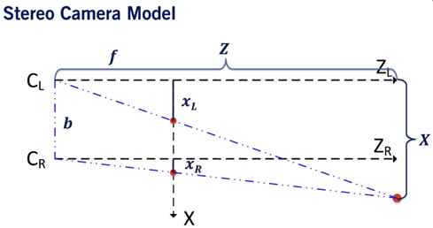
- xL corresponds the the point in the left camera image. xR is the same for the right image.
- b is the baseline, it’s the distance between the two cameras.
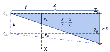
Left Camera Equations
👉 Z = X*f / XL
- For the right camera:
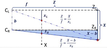
Right Camera Equations
👉 Z = (X — b)*f/ XR
Put together, the correct disparity d = XL — XR
Z is inversely proportional to XL — XR, that is, the smaller the depth, the greater the parallax, and the closer the object has greater parallax. This is why the closer objects in the disparity map are darker.
Human vision system also produces parallax error, which occurs when an image is seen from two different lines of sight and as a result, the object appears to move. For objects that are closer, parallax error is more pronounced, indicating a large disparity as the same point appears in different locations from both projections. Due to the inverse relationship, it must correspond to a short depth.
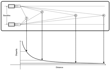
An inverse correlation exists between the shift of the point and the distance of the object from the camera, i.e the larger the point’s movement, smaller will be the distance of the object from the camera.
Thus Disparity values obtained from stereo image pairs are directly proportional to the distance the cameras are apart and inversely proportional to the distance an object is away from the two cameras.
What is disparity?
Disparity is the difference in image location of the same 3D point from 2 different camera angles.
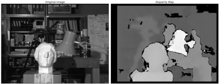
To compute the disparity, we must find every pixel from the left image and match it to every pixel in the right image. This is called the Stereo Correspondence Problem.
Stereo Correspondence solution:
- Take a pixel in the left image
- Now, to find this pixel in the right image, simply search it on the epipolar line. There is no need for a 2D search, the point should be located on this line and the search is narrowed to 1D.
· This is because the cameras are aligned along the same Y and Z axis.
Depth Estimation:
- Decompose the projection matrices into the camera intrinsic matrix 𝐾, and extrinsics R, t.
- Get the focal length f from the 𝐾 matrix
- Compute the baseline 𝑏 using corresponding values from the translation vectors 𝑡
- Compute depth map of the image using the following formula and the calculated disparity map d as:

